 Turkish Accelerator and Radiation Laboratory (TARLA) Think Future, Think TARLA
Helium Cryogenic System
The helium cooling system has been established to lower the temperature of niobium cavities to 1.8 K (-271.4 °C) at 16 mbara in order to transition the two superconducting radio-frequency (SRF – 9-cell TESLA cavities) cryomodules into the superconducting phase at TARLA.
The pre-cooling of the system and the thermal insulation of components that need to operate under cryogenic conditions are provided by liquid nitrogen (LN2). Liquid nitrogen is stored in a double-walled vacuum jacket storage tank with a volume of 25 m³. The thermal insulation of cold box 1, cold box 2, cryomodules, and cryogenic transfer lines is also provided with high vacuum.
The helium cryogenic system in the facility operates on a closed-loop principle. With pre-cooling by Liquid Nitrogen (LN2), the system has a total cooling capacity of 180 W (1.8 K @ 16 ± 0.01 mbar). It also has the capacity to produce approximately 45 L/h of liquid helium LHe(I) at 4.5 K (-268.7 °C) and 1.3 bara, and a cooling capacity of 40 W @ 1.8 K, without LN2 pre-cooling.
General Information about System Components
Helium Gas Tanks: Two helium buffer reserve tanks with a volume of 50 m³ each are equipped with vacuum jackets and store helium in the gas phase. These tanks generally store helium at 10 bar pressure and room temperature, providing 5.0 grade (99.999% purity) helium gas to the system or for storage when the system is closed.
Compressor Unit: It consists of two screw-type helium compressors, each with a power of 140 kW. These compressors ensure that the helium reaches Cold Box 1 (CB1) within a pressure range of ~14.0 – 14.5 bara before the cooling process begins.
Oil Removal and Gas Management System (ORS and GMS):
The oil removal system separates helium mixed with oil from the screw block of the helium compressors, as well as removing other particles (if any). It consists of two coalescer-type filters, one active charcoal filter, and one carbon separator filter.
The gas management system controls the flow of helium gas between the gas tanks, compressors, high-pressure line, and low-pressure line using three positionable automatic throttling control valves.
Cold Box 1 (CB1): The Cold Box 1 (CB1) works as a “Refrigerator” in both “Refrigeration/Liquefaction” modes. It operates based on the Collins Cycle (modified Claude Cycle) principle with two turbo expanders with static gas bearings in series. By using its Joule-Thomson Valve, helium gas, which has been cooled below the inversion temperature, is liquefied, and stored in a 1000 L liquid helium tank at 1.3 bara and 4.5 K (-268.7 °C). The system uses high-vacuum insulation (HV) to protect it from thermal effects. Additionally, It provides the initial pre-cooling of helium gas using liquid nitrogen through its three-steam first heat exchanger (HX1), allowing the system to be operated either with or without LN2 pre-cooling.
Storage Tank (Dewar): A 1000 L vacuum-insulated liquid helium tank (dewar) is where the LHe(I) (liquid helium phase at 1.3 bar and 4.5 K) is stored before being delivered to the cryomodules.
Cold Box 2 (CB2): In transferring the accumulated LHe(I) from the dewar to the cryomodules, it utilizes the cold power of the cold helium gas exiting the cryo-modules in CB1, cooldowns the LHe(I) transferred from the dewar to the cryomodules down to ~2 K (-271.2 °C), and also facilitates the transfer of warm helium gas to the Warm Vacuum Pumps Unit. The system is isolated using high-level vacuum and liquid nitrogen thermal shielding.
Designed in such a way that it distinguishes it from other helium cryogenic systems:
• Bieri heat exchanger (HX), designed to work within a temperature range of -269 °C to +65 °C and pressures from -1 bar to 19 bar,
• A subcooler heat exchanger that operates in the 1.6 K to 4.5 K (-271.6 °C to -268.7 °C) range,
• A cold compressor, and
• Two Joule-Thomson valves,
which together enable the delivery of superfluid liquid helium (LHe(II)) at 1.8 K (-271.4 °C) to the cryomodules.
Warm Vacuum Pumps Unit (WVP): The unit, equipped with five integrated oil-lubricated rotary vane and root pump groups, maintains the pressure of the liquid helium filling the titanium vessels surrounding the superconducting radio-frequency (SRF) cavities within the cryo-modules at 16 mbar, ensuring the formation and continuity of the 1.8 K (-271.4 °C) LHe(II) phase.
Transfer Lines: These are vacuum-insulated lines, which, in addition to vacuum insulation, can also be nitrogen-cooled, facilitating the transfer of helium in either the gas or liquid phase between subunits of the system. Known as MCTL (Multi Cryogenic Transfer Lines), these lines enable the transfer of multiple cryogenic fluids or, as in the case of the TARLA System, the use of LN2 for thermal insulation, ensuring that liquid helium is minimally affected by heat over long distances with vacuum insulation.
RF Systems
The accelerator infrastructure heavily relies on high-power and low-level RF systems. High-power RF (HPRF) modules deliver RF energy to superconducting and normal conducting cavities. The schematic structure of the RF system is illustrated in the figure.
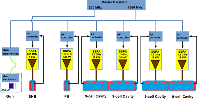
At TARLA, a 1 mA electron beam is accelerated to 40 MeV using superconducting structures operating at 10 MV/m. High power RF system includes four TESLA-type superconducting cavities powered by solid-state RF amplifiers, each capable of 18 kW output. The injector features two normal conducting RF cavities.
The Low-Level RF (LLRF) system regulates the amplitude and frequency of RF signals delivered to the cavities and synchronizes beam-RF interaction. LLRF supports:
- A 260 MHz subharmonic buncher (SHB)
- A 1.3 GHz fundamental buncher (FB)
- Four 1.3 GHz TESLA superconducting cavities
The LLRF system is fully digital and includes six RF station controllers, each integrated with mechanical tuner control units. Additional modules such as the Local Oscillator Generation Module (LOGM) and Drift Compensation Module (DCM) are essential for signal generation and drift correction.